


详细参数:
电源电压:DC4.5-6V (micro USB接口)
工作电流:不超过70mA
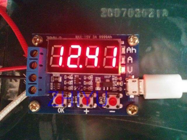
放电电压:1.00V-15.00V 分辨力0.01V
终止电压范围:0.5-11.0V
支持通过电流:最大3.000A 分辨力0.001A
电压测量最大误差:1%+0.02V
电流测量最大误差:1.5%+-0.008A(老版)
电流测量最大误差:1.2%+-0.002A(在售)Detailed parameters:
Supply voltage: DC4.5-6V (USB micro interface)
Working current: no more than 70mA
Discharge voltage: 1.00V-15.00V resolution 0.01V
Termination voltage range: 0.5-11.0V
Supported by current: maximum 3.000A resolution 0.001A
Voltage measurement error: 1%+0.02V
Maximum error in current measurement: 1.5%+-0.008A (old version)
Maximum error in current measurement: 1.2%+-0.002A (on sale)
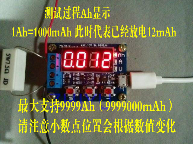
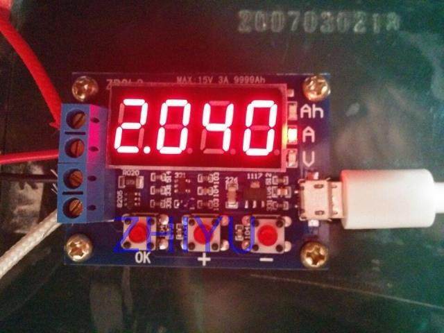
最高电池容量范围:9999Ah(1Ah=1000mAh)数值较大是通过小数点移位切换,当低于10Ah时显示为X.XXX ,达到10Ah以上显示为XX.XX,以此类推。
电路板尺寸:50mmX37mm
成品尺寸:50mmX37mmX17mm (长X宽X高 最大位置尺寸,包含铜脚高度)
板及配件重量:单板28g(包括铜柱),两只5W陶瓷电阻9g,50W电阻约27g(含线)
注意:本电路为了提高电压测量精度,特别设计了直流偏置,当端子什么都不接时会显示一个很小的电压,并不影响实际测量,如果您短接输入端子(绝对0V)就会显示0。想弄懂原理的可以去查阅电工学里的叠加定理。
使用方法:
1.被测电池应当首先充满电。
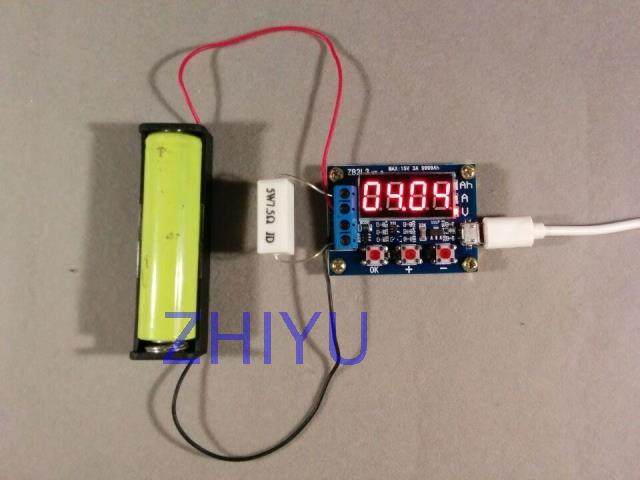
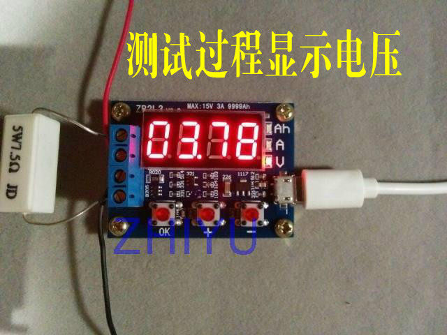
2.连接被测电池正极到输入正,负极到输入负极,不可接反(带负载接反可能会损坏电路)!连接负载至输出正极和输出负极,给测试仪micro USB通工作电源(不可用台式机或者笔记本USB供电),此时显示电池电压。
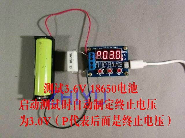
3.直接启动测试只需要按动一下“OK”按键,测试仪能够根据电池满充电压自动制定合适的终止电压,并会闪烁显示3次后启动测试。需要人工制定终止电压只需要在电池电压显示状态下按动“+”或“-”按键修改,终止电压显示为P开头,后面代表电压值,分辨率0.1V,设定好后按动“OK”开始测试。
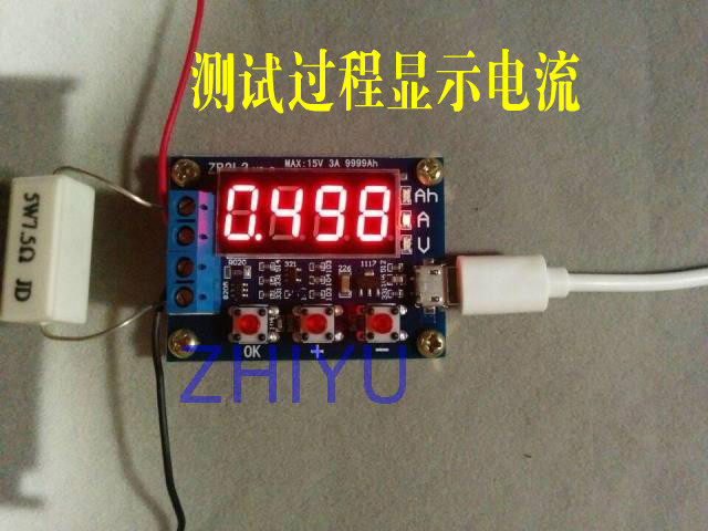
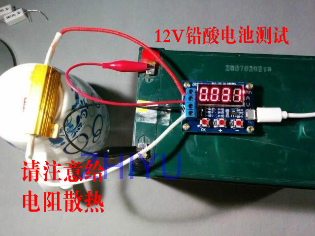
4.测试开始后测试仪会接通控制负载的电子开关,测试过程数据显示会在放出容量(Ah),当前放电电流(A)以及电池电压(V)之间轮显。当电池电压到达设定终止电压后,测试仪切断负载控制开关,显示数据停留在容量(Ah)上面并且和对应指示灯一起快速闪烁,此时显示的容量就是电池的实际放电容量,按动一下“OK”可以终止闪烁让数据稳定显示,再次按动“OK”按键恢复到刚上电状态可以更换电池测试下一节……
错误代码及含义:
Err1:电池电压高于15V
Err2:电池电压低于设定终止电压
Err3:电池无法承受负载放电电流或者线路内阻太大
Err4:电流过大(电流超过3.1A)
Err5:使用不当或者接线错误已经导致设备烧毁无法使用(电流取样或者控制开关MOS烧毁)
二次校准操作(自行运行校准后,则代表放弃保修):
同时按住三个按键给测试仪通电,进入校准模式,首先显示校准记录次数之后进入正式校准采样程序显示0u0A,此时短接输入正负极后按动一下“OK”按键,完成显示J10u,给输入正负极之间施加10.00V标准直流电压后按动一下“OK”按键,之后显示J2.0A,给输出负极(流入方向)和输入负极(流出方向)施加2.0A恒定直流电流后按动一下“OK”按键完成校准。测试仪会对校准数据进行预审核,如果校准数据靠谱,则会依次显示4个校准数后退出,如果预审核认为数据不靠谱,则丢弃数据退出。
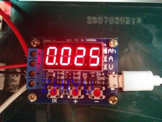
部分使用图片:
The highest battery capacity range: 9999Ah (1Ah=1000mAh) is larger by the decimal point shift switch, when below 10Ah shows X.XXX, above 10Ah shows XX.XX, and so on.
Circuit board size: 50mmX37mm
Finished size: 50mmX37mmX17mm (length X width X high maximum position size, including copper foot height)
Weight: veneer board and accessories (including two pillars), 28g 5W ceramic resistance 9g, 50W resistance of about 27g (including line)
Note: this circuit in order to improve the voltage measurement accuracy, especially the design of a DC bias, what does not answer when the terminal will display a small voltage, does not affect the actual measurement, if you are short circuited input terminals (absolute 0V) will display 0. Want to understand the principle can look in the electrical engineering superposition theorem.
Usage method:
1 the battery should be charged first.
2 connect the positive electrode of the battery to the positive electrode of the battery, and the negative pole to the input negative pole! Connect the load to the output positive and negative, to the test instrument USB micro working power supply (not available desktop or notebook USB power supply), the battery voltage at this time.
3 direct start testing only need to press the "OK" button, the test instrument can automatically set according to the battery full charge voltage suitable termination voltage, and will display 3 times after the start of test. Need to set up the termination voltage only in battery voltage display state press "+" or "-" button to modify, terminate voltage display at the beginning of P, behind the representative voltage value, the resolution of 0.1V, set up after the press "OK" to start the test.
4 testing starts after the tester will switch on the control load of the electronic switch, the test process data show that the discharge capacity (Ah), the current discharge current (A) and the battery voltage (V) between the wheel. When the battery voltage reaches the set voltage after the termination of tester off load control switch, display data stays in the capacity (Ah) and above and the corresponding indicator light flashes quickly with the actual discharge capacity, the capacity of the battery is displayed, press the "OK" can stop flashing make stable data display, press "OK" again the key to recovery just on the power state can replace the battery test section......
Error code and meaning:
Err1: the battery voltage is higher than 15V
Err2: the battery voltage is lower than the set termination voltage
Err3: the battery can not afford load discharge current or line resistance is too large
Err4: the current is too large (more than 3.1A)
Err5: the use of improper or wiring errors has led to the device to burn can not be used (current sampling or control switch MOS burning)
Two calibration operations (after their own calibration, the representative to give up the warranty):
At the same time, press three keys to test electricity, enter the calibration mode, the first display calibration record number of times after entering the formal calibration sampling procedures showed that 0u0A, the short pole is connected with the input after the click "OK" button to complete the display, J10u, to the positive and negative 10.00V standard applied between the input DC voltage after the click "OK" button after the show, J2.0A, to the output anode (inflow direction) and negative input (flow direction) under 2.0A constant DC current after the click "OK" button to complete the calibration. Test calibration data will be pre audit, if the calibration data is reliable, it will in turn show the 4 calibration number after the exit, if the pre audit that the data is not reliable, then discard the data exit.
Part of the use of pictures: